Self-test – EN 62034 – autotest IV
The standard EN 62034 states the minimum requirements for how an automatic test system should work. The Autotest IV self-test system, which Fagerhult can offer in the majority of products, fulfils the requirements in this standard.
The Autotest IV system builds on decentralised intelligence, i.e. emergency lighting units in the system work entirely independently, both of each other and of a centrally monitored system.
Automatic test checks that:
- there is a connection to the mains supply.
- the battery is connected to the electronic unit.
- the battery has sufficient capacity.
- the battery charge is working.
- the light source for emergency lighting is intact.
- the electronic components are working fully and that the emergency lighting circuits themselves are intact.
Installation test
Autotest IV conducts this test automatically as soon as the system is connected to the mains and the battery has been fully charged, which takes 24 hours.
During the test, the installation is placed into emergency mode during its full indicated operating time i.e. 1 or 3 hours depending on the choice of product. Then the battery is recharged for 24 hours. Once this process has been completed, and no faults have been indicated, the installation can be put into use.
Monthly test
Each month a shorter function test is carried out which takes 30 seconds.
Annual test
The annual test performs a similar undertaking to the installation test. This is the test where any maintenance requirements of the emergency lighting facility is normally discovered.
Displaying status – status diode
Emergency lighting products are equipped with a two colour LED which switches between green and red light depending on the actual status, as indicated in the chart below. Faults are also indicated via a built-in acoustic signal every 35 minutes (not connected with a DALI connection).
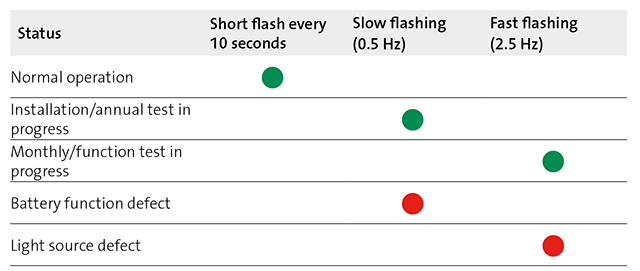
Emergency lighting products are equipped with a two colour LED which switches between green and red light depending on the actual status. The LED indicates the status according to the table. Faults are also indicated via a built-in acoustic signal every 35 minutes (not connected with a DALI connection). In addition, if the system is based on the use of potential free contacts or DALI communications, an alarm is also received on the monitoring system. The fault indication remains until the fault has been rectified.
Reset – resetting the self-test system
When the fault has been rectified, the test system must be reset to the normal setting by switching off the mains supply twice within 5 seconds. An automatic short function test is then made. The system can also be reset via a DALI command so the mains is not switched off.
There are two versions of Autotest IV available.
One-way communication – potential free contact
The possibility to connect to an external master system via a potential free alarm contact.
Two-way communication – DALI
Communication via DALI protocol. The system is either connected to a separate DALI panel (e.g. e-touchBOX), to a central PC connected to e-touchPANEL or to a bigger system (e.g. winDIM@net).
Each emergency lighting luminaire in a DALI system receives its own unique address which means that a connected unit can easily be identified/named. Connected units can also be grouped, which makes it possible to carry out a selected test of certain emergency lighting luminaires, e.g. everything in a specific corridor. In such cases the building does not have to be evacuated in connection with the test.
The DALI system provides duplex communication, meaning that unlike the system based on the potential free contact, the cause of fault is visible on the master system. This also applies when initiating the function test via DALI and resetting the test system. Tests are carried out according to an integrated calendar in the emergency lighting units or at time points indicated in the master system.
Disconnected master system – not connected
The emergency lighting units intended for external surveillance via potential free contact or via DALI do not depend on having a master system connected or functioning. Necessary tests are still carried out according to the emergency lighting unit’s own integrated calendar. This also applies to the DALI version.
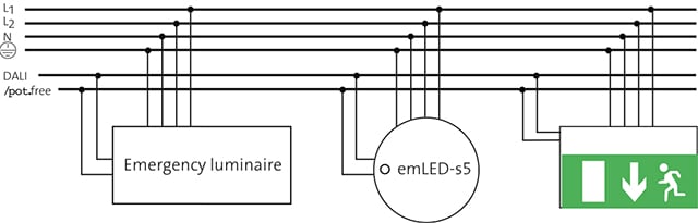
General connection diagram for emergency lighting.
- Emergency lighting luminaires that work as a normal on/off luminaire in normal operation and as emergency lighting in emergency operation.
- emLED-s5 which are only operated in emergency mode.
- Safe condition signs for continuous operation.